1-1 Principle of Capacitor Construction
The principle construction of a parallel plate capacitor is shown in Fig.l.
When a voltage V is applied between the conducting electrodes placed opposite to each other, a certain amount Q of electric charge proportional to the voltage can be stored on the surfaces of the dielectric. The proportional constant is called capacitance C, designating the ability of a capacitor to store energy in an electric field.
Q=C.V Q: Charge(C) V: Voltage (V) C: Capacitance (F)
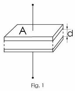
The capacitance C of capacitor can be expressed by the following equation:
C = ε0 • ε • A/d
ε:dielectric constant
ε0: dielectric constant in vacuum (= 8.85x10⁻¹² F/m)
A: electrode area [m2]
d: electrode distance [m]
The dielectric constant of an aluminum oxide layer is 7 to 8. Larger capacitances can be obtained by enlarging the electrode area A or by reducing the distance d.
Table 1 shows the dielectric constants of typical dielectrics used in capacitors. In many cases, capacitor names are related to their dielectric material used, for example, aluminum electrolytic capacitor, tantalum capacitor, etc.
Table 1
Dielectric | Dielectric Constant | Dielectric | Dielectric Constant |
Aluminum oxide film | 7 to 8 | Porcelain(ceramic) | 10 to 120 |
Mylar | 3.2 | Polypropylene | 2.2 |
Mica | 6 to 8 | Tantalum oxide film | 10 to 20 |
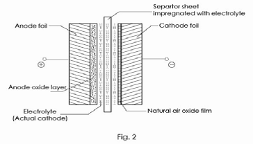
Aluminum electrolytic capacitors offer large volumetric capacitance values, because the anode electrode’s surface is roughened by electrochemical etching, enlarging its area by factor of 20~100 compared to plain foil, and also because the dielectric layer is very thin (1.4 nm/V).
The schematic cross section of an aluminum electrolytic capacitor is shown in Fig. 2
1-2 Equivalent Circuit of the Capacitor
The electrical equivalent circuit of the aluminum electrolytic capacitor is given in Fig.3
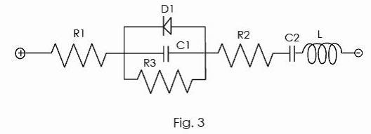
R1: Resistance of terminal and electrode
R2:Resistance of anode oxide layer and electrolyte
R3:Insulation resistance because of defective anodic oxide layer
D1: Oxide semiconductor of anode foil
C1: Capacitance of anode foil
C2: Capacitance of cathode foil
L: Inductance caused by terminals, electrodes, etc.
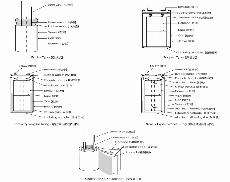
1-3 Structure of aluminum electrolytic capacitor
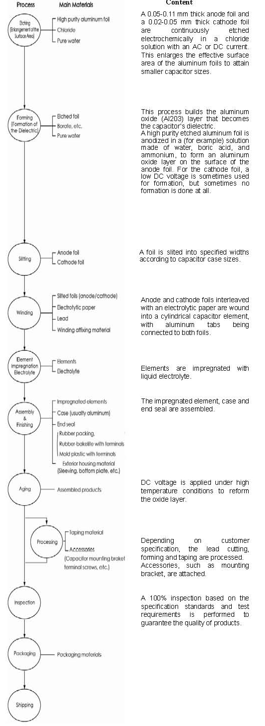
1-4 Manufacturing process of aluminum electrolytic capacitors
1-5 Basic parameters and terms
1-5-1 Capacitance:
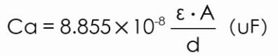
The capacitance of the dielectric portion of the anode aluminum foil can be calculated with the following formula :
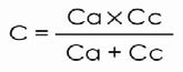
The cathode foil capacitance Cc depends on the dielectric properties of the oxide layer which was either deposited by a forming voltage or which grew naturally during storage (typically, the voltage proof of the cathode oxide layer is 1V or less). According to the construction of aluminum electrolytic capacitors, Ca and Cc are connected in series. Therefore, the total capacitance can be determined by the following formula:
The standard capacitance tolerance is 20%(M); however, capacitors with a capacitance tolerance of 10%(K), etc. are also manufactured for special usage. The capacitance of aluminum electrolytic capacitors changes with temperature and frequency of measurement, so the standard has been set to a frequency of 120Hz and temperature of 20°C.
1-5-2 Dissipation factor(Tanδ)
The Tanδ is the ratio of the resistive component (RESR) to the capacitive reactance (1/ωC) in the equivalent series circuit.
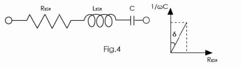
Tanδ= RESR/ (l/ωC)=ωC RESR
where : RESR=ESR at 120Hz
ω = 2TTf
f= 120Hz
The Tanδ shows higher values as a measuring frequency increases and a measuring temperature decrease.
1-5-3 Equivalent series resistance (ESR)
The equivalent series resistance (ESR) represents all of the ohmic losses of the capacitor. In the equivalent circuit, it is connected in series with the capacitance. The ESR originates from the ohmic resistances of the electrode foils, the electrolyte, the leads and each internal connection.
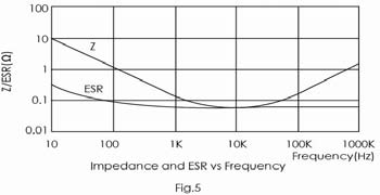
The ESR declines with increasing temperature, and also declines steadily with increasing frequency at low frequencies.
1-5-4 Impedance (Z):
The impedance is the resistance which opposes the flow of alternating current at a specific frequency. It is related to capacitance (C) and inductance (L) in terms of capacitive and inductive reactance, and also related to the ESR. It is expressed as follows:
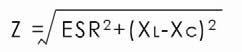
Where: XC=1/ωC=l/ 2TTfC
XL =ωL=2TTf L
A typical impedance-versus-frequency curve is shown below. It takes on its minimum value at the self-resonant frequency, and the impedance is equal to the ESR at that frequency.
1-5-5 Leakage current:
Leakage Current is the DC current flowing through the capacitor with the rated voltage applied. The value of leakage current depends on the voltage applied, the charging period and capacitor temperature. The leakage current shows higher values as the temperature and voltage increase.
The leakage current value can be decreased by proper selection of materials and production methods; however, cannot be totally eliminated.
The specified leakage current value is measured after the rated voltage of the capacitor is applied at room temperature for a specified time period.
1-5-6 Ripple current
Ripple current is the alternating current flowing through a capacitor. This current causes an internal temperature rise due to power losses in the capacitor. The rated ripple current are specified for an expected temperature rise at rated temperature, under which the capacitor will operate normally during the whole lifetime period.
Generally, the 85°C type capacitors permit a temperature rise of 10°C and have a maximum permitted core temperature of 95°C . The 105°C type capacitors permit a temperature rise of 5°C and have a maximum core temperature of 110°C. Actual maximum permitted core temperatures vary by type and manufacturer.
When operating temperature decreases, the maximum permitted core temperature rises, in the other word, the rated ripple current could be increased when the actual operating temperature is less than the rated temperature. However, too much temperature rise will cause the capacitor to exceed its maximum permitted core temperature of each ambient temperature and fail quickly, operation close to the maximum permitted core temperature will dramatically shorten expected life. The following shows a guide limit of maximum core temperature rise (△T) at each ambient temperature for a 105°C maximum rated products.
Ambient temperature Ta (°C) | 40 | 55 | 65 | 85 | 105 |
Guide limit of △T (°C) | 30 | 30 | 25 | 15 | 5 |
Core temperature Ta + △T | 70 | 85 | 90 | 100 | 110 |
In most applications, there is more than one frequency for the ripple current. In this cases, the r. m. s . (root mean square) value of the ripple currents needs to be considered, because currents of all frequencies contribute to the self-heating:
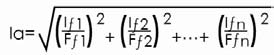
la: r. m. s . value of the rated ripple currents
If1 ••• Ifn : r .m. s .values of ripple currents at frequenciesf1 •••fn
Ff1••• Ffn : correction factor for the current at frequencies fl •••fn

where ƒo= reference frequency of the nominal
ripple current
The typical frequency multipliers are shown in the specification.
1-5-7 Rated Voltage
Rated voltage is the maximum peak voltage including ripple voltage that may be applied continuously between the terminals of the capacitor over the specified temperature range. When a ripple current is applied to the capacitor, the sum of the peak ripple voltage and the bias DC voltage should not exceed the rated voltage, namely UIP+UB≤UR, where:
UIP: peak ripple voltage
UB : bias DC voltage
UR: rated voltage
Capacitors with higher rated voltage could replace the lower rated voltage capacitors as long as case size and electrical perfomances are also compatible.
1-5-8 Recovery Voltage (Dielectric Absorption)
After charging and then discharging aluminum electrolytic capacitors, a voltage between the two terminals will appear after some time. This voltage may reach levels of 15~25% of the originally applied voltage and it is called recovery voltage. Its existence is related to the phenomenon of dielectric absorption.
Once the recovery voltage is present, sparks may scare the workers during assembly, and low-voltage components (CPU, memory, etc.) may be affected. Measures to prevent this are to discharge the accumulated electric charge by a resistor of about 100Ω to 1kΩ before usage, or to ship out the capacitors with short-circuited terminals, e.g. by covering them with an aluminum foil or a conductive plastic cover at the production stage. Please consult us for adequate procedures.